Sustainable Clean-In-Place: Methods, Insights & Innovations

Discover strategies to optimize CIP systems and cut water, energy, and chemical use—boosting sustainability and efficiency in hygienic processing.
A clean-in-place (CIP) system is among the largest users of consumables at a hygienic processing plant. Presented here are tips for reducing the consumption of water, chemicals and time in CIP operations.
In many industries there is a burgeoning awareness and pursuit of financially justifiable resource conservation. The cleaning routines that make sanitary processing possible are among the largest users of consumables in a facility. Clean-in-place (CIP) is the automated approach of cleaning process equipment with minimal manual intervention. It is one of the most important aspects of hygienic production; however, many plants ignore CIP procedures unless issues arise. Due to this oversight, opportunities to make CIP more sustainable are lost. Optimized CIP programs not only ensure product integrity, but also provide valuable savings through the conservation of water, energy, chemicals and available production time. There are many process design philosophies, mechanical components and automation solutions that make this not only feasible but cost effective.
Benefits of practicing CIP
CIP is practiced in industries where hygienic production is necessary to produce product that is pure and safe to consume or use. Historically, cleaning of hygienic processes was achieved by hand through very labor-intensive procedures for which it was difficult to ensure repeatability. With the advent of CIP, available production times increased as plant-wide shutdowns for disassembly and cleaning were no longer required. Today, individual processing units can be isolated and cleaned independently without impact to production in other areas, allowing for continuous 24-hour production. Worker safety has improved by reducing high-risk activities, such as confined space entry and disassembly of pipes that could be pressurized or contain cleaning chemicals. The widespread acceptance of CIP in the food and beverage industries, along with advancements in implementation practices, has led to further acceptance into other industries. The pharmaceutical and biotechnology industry standards rely on these repeatable processes that can be validated. The design and prescribed CIP regimen of a given process can be refined to minimize the use of consumables without degrading total effectiveness.
Example of a typical CIP application
To understand where potential savings exist, it is necessary to understand a typical CIP cleaning approach (Figure 1). Cleaning recipes do vary by industry but are founded on the same principles. CIP relies on time, temperature, chemical action and mechanical force. In general, water-based solutions are used to remove residual product from the process equipment. After initial water rinses, a heated dilute caustic solution is circulated, followed by an acid solution and a final rinse. Caustic is the primary cleaner and breaks down proteins and fats. Acid or acid sanitizers neutralize residual caustic and prevent mineral buildup on the equipment, improve drying, and can create a surface condition that inhibits bacterial growth. Acid washes are commonly substituted in food plants with the practice of storing process lines in sanitizer.
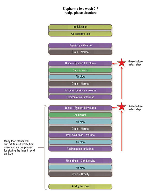
Figure 1: Shown here is a typical two-wash CIP recipe phase structure for a biopharmaceutical plant
For tanks and equipment with large internal cavities, static spray balls supply cleaning solution to the top of the tanks, resulting in a turbulent sheeting action down the sidewalls. Piping with in-line components, such as pumps, valves and instrumentation, are cleaned at a minimum velocity to ensure fully flooded lines, which guarantees full chemical contact and maintains a suspension of settled solids. High-pressure dynamic spray devices remove viscous product from vessels. When selecting these devices, the supply pressure requirements are often much higher, the rotation of the spray device may need to be tracked via proximity switch, and the process lines supplying the vessel still must clean at the proper flowrate, which may exceed that of the tank spray device requirement.
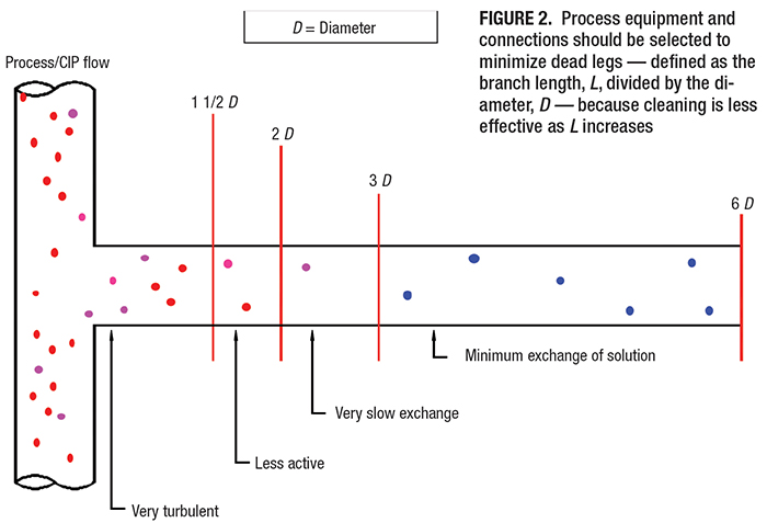
There are multiple hardware advances to improve cleaning effectiveness and reduce waste. Many of these reduce CIP dead legs in length (Figure 2). A dead leg is defined as the length of a branch ( L) divided by the internal diameter ( D), or L/ D. The industry standard for CIP cleanable connections is less than 2 L/ D. Empirical tests confirm that the shorter the L/ D, the quicker the dead leg rinses. Branches, such as instrument tees, should be installed in the horizontal to prevent trapped air from compromising solution contacting all surfaces. It is important that the system is designed with cleaning in mind from the start for CIP to work effectively.
Recent developments in technology and industry practices are being leveraged to drive success in the area of sustainability. Production facilities focusing on conservation have effectively integrated CIP via new mechanical and automation solutions to foster more economical practices.
Achieving sustainable CIP
The most impactful approach to achieving sustainable CIP is by integrating the practices early on in the design of a new plant or expansion. Location and piping size. Considerations, such as locating the CIP units central to the largest users, will minimize dedicated CIP piping. This reduces hold-up volume in the piping, which is filled several times during each cleaning cycle. The excess volume is a function of CIP design, but has no bearing on its effectiveness. Essentially, this physical volume is a fixed cost of performing CIP, regardless of the level of residual soil in the equipment being cleaned.
For systems that are cleaned multiple times a day, such as product tankers, a CIP unit in close proximity can save recurring costs. For example, in a milk plant that receives 54 milk tankers to sustain a 325,000-gallon daily production, the CIP units were grouped in one area near the utilities rather than near the process loads. The tanker receiving-bay CIP unit was 130 ft away and estimated to consume 6.2 million gal/yr of water. By moving CIP units within 40 ft of the receiving area, the line lengths were shortened by more than half the original length, with water consumption reduced to 3.3 million gal/yr. Additionally, 11,000 gal of high-strength acid and caustic chemical usage was conserved. The reduction in water, energy, chemicals and waste stream effluent to be treated resulted in a savings of $125,000 per year. Considering the lifespan of facilities, the careful placement of CIP systems close to users can result in savings that more than offset the initial capital cost.
Another important consideration in a new facility is to take the extra time to properly size the CIP distribution piping and associated supply and return pumps to design a system that is functional, yet not oversized for the cleaning demands. In the previous study, 1.2 million gal/yr of water and 10,000 gal/yr of high-strength chemical were estimated to be saved by downsizing the piping from a 3-in.-dia. line to a 2.5-in.-dia. line.
Product recovery and instrument optimized rinses. In the case of existing plants, where resizing piping and moving or adding additional CIP units may be impractical, there are still many opportunities to improve CIP sustainability. Product recovery options, such as air blows, water pushes and product recovery systems, can help plants reclaim a majority of the product remaining in the lines. When paired with CIP, less water is used in the first rinse to flush the process piping. This two-fold effect provides plants with more usable product for sale and a reduced water usage.
Product recovery water pushes can be sourced from a CIP unit or designed functionality in valve arrays. Turbidity sensors placed at the end of transfer lines or at the CIP return (CIPR) measure the rinse water optical density (Figures 3 and 4). The commissioned change in opacity will determine when the product-water interface has passed. Due to turbulence-induced mixing as a function of distance, this interface becomes elongated and can be thought of in three distinct regions: product, product-water mixture, and water (Figure 3, bottom). For each region, a different condition is programmed and flow diverted accordingly. When product is encountered by the turbidity sensor, the process line remains open and the residual product is recovered with the rest of the batch transfer. For the water-product mixture, flow can be diverted to an “Ag system” for storage and distribution as livestock feed. Because the diluted product still has nutritional value, it can be sold for profit to farms, reducing the facility’s water-treatment costs. Flow is diverted to the drain when water is detected, and the CIP unit moves to the next step in the CIP program.
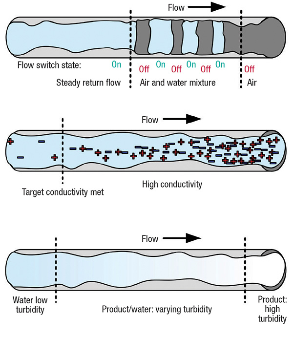
Figure 3. Return flow switches, conductivity probes and turbidity sensors are used to efficiently transition CIP operations
Following a chemical wash, an analytical sensor located at the CIPR measures conductivity of the rinse solution. The rinse phase concludes once the conductivity drops below the set threshold for a duration. The sufficient amount of rinsing is performed for each circuit without a fixed excess volume built in for robustness.
In process lines where the risk of cross-contamination between allergens is nonexistent, a reuse CIP system may be used (Figure 4, top). Unlike in single-use CIP (Figure 4, bottom), where cleaning solutions are made up once, used, and disposed, a reuse CIP system recycles them as a pre-rinse for future cleaning. The chemical recapture at the reuse CIP skid is akin to the process water push approach.
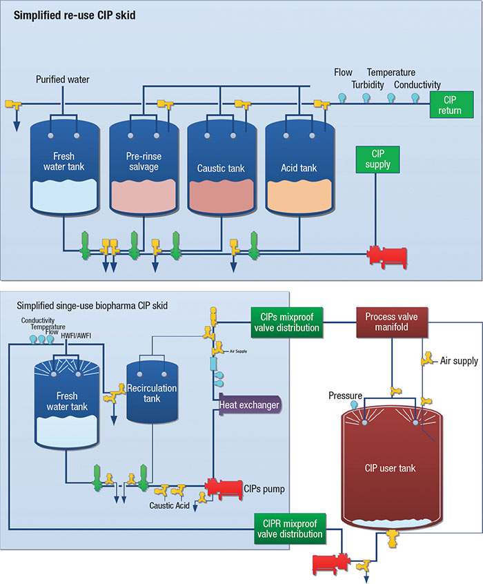
Figure 4. Shown here are two examples of CIP circuits with associated hardware and instrumentation. Such circuits can be designed to reuse cleaning solutions (top) or for single-use CIP (bottom)
With the use of both turbidity and conductivity sensors (Figure 3), CIP systems can now be tailored to specific products and process lines, ensuring excess water is not flushed down the drain after piping has been rinsed. Return flow switches are also installed at times to confirm that water has been received back to the CIP skid. Performing a return flow check early on in the cleaning cycle for system integrity is desirable before investing more time before a secondary alarm results in the failure. Periodically confirming the calibration of the sensors will improve their efficacy.
Process modeling. Generating schedules from process models with system user participation to determine realistic requirements and avoid bottlenecks is paramount. Equipment utilization can be managed more efficiently when activities are modeled in concert. The more constraints included and degree of granularity pursued, the more valuable the model will prove to be. Benefits yielded from the exercise include the ability to anticipate future capital projects, properly staff and negotiate equipment conflicts.
Process models can also include pictorial representations (Figure 5) of automated operations on piping and instrumentation diagrams or schematics known as color code drawings. Generating color codes can visually represent complex processes and allow streamlining of automation sequencing. The drawings can be referenced to clearly communicate between process and automation groups while also facilitating commissioning and training.
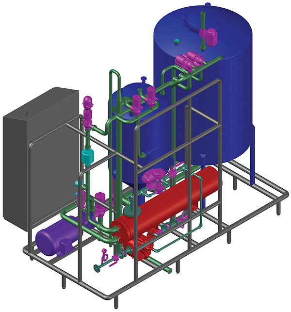
Figure 5. Shown here is a 3-D model of a single-use clean-in-place (CIP) skid with a tulip recirculation tank
Disposable equipment can eliminate cleaning from the equation. Single-use equipment, as used in the biotech industry, eliminates the need for cleaning and steaming. Using pre-sterilized bag vessels and filters can increase overall equipment effectiveness. When considering a new facility, the cost of bags can have a better return on investment than fixed tanks with CIP, steam in place (SIP), water, waste, chemicals and other utilities. The avoided costs of cleaning validation and commissioning time are added major benefits. On an existing facility, implement disposables judiciously to increase production without adding equipment. Also, the process space can be more dynamic, more easily accommodating future products of smaller batches with unique unit operation configurations. A hybridized process design can utilize the benefits of both approaches while remaining scalable.
Connectors to reduce vessel dead legs. Vessels can have internal dead legs if attention is not put into initial equipment designs. Sidewall and tank top connections are traditionally 2-in. long clamp connections, which can be difficult to reach with a spray device. Short, machined outlet ferrules reduce the dead leg to generally less than 0.5 L/ D. Recessed connections can prove challenging during coverage testing. Tank head ports should be accessibly grouped in a circular arrangement around spray devices to allow for more favorable spray angles. Otherwise, custom spray patterns are usually required, as well as increased flowrates, to ensure solution reliably makes contact with all internal surfaces. The water sheeting on the sidewall of a vessel during CIP is usually sufficient to wet the short outlet ferrule connection surfaces.
Self-priming liquid-ring pumps improve CIP robustness. The CIP return (CIPR) path portion of a circuit is prone to have hydraulic issues, as vessels are kept as empty as possible during cleaning. A small puddle in a non-vented vessel will trap positive pressure in the tank and reduce more water buildup. The water pressure properties are equivalent to a column of water stuffing the CIPR pump. Less water in the vessel reduces overall resources expended for the CIP. Occasionally, a mixture of air will be present in the outlet line from a vessel, causing some centrifugal pumps to lose pumping capacity from cyclical air binding.
A liquid-ring pump facilitates this by being capable of pumping air and water. Liquid-ring pumps usually have a higher net positive suction head required (NPSHr) than conventional centrifugal pumps. This exacerbates the fact that they can compromise their upstream stuffing conditions by generating a strong enough vacuum in unvented vessels to the point where they no longer pump. This concern is especially present when pumping hot solutions where the vapor pressure of the liquid approaches boiling. The vessel should be vented, or make-up air should be added to avoid net positive suction head available (NPSHa) issues at the return pump.
Pre-rinses targeted at the dirtiest piping first. During CIP, the process valves cycle to ensure solution is directed down each path. Most programs have a single flow sequence that includes all targeted pathways. There are many ways to structure the valve sequencing to reduce consumption. One quick method is to deploy targeted pre-rinses or reduced chemical concentration washes to the bulk soil load paths to drive residual product out of the system. Isolating the high-soil paths will prevent the spread of soils on additional system surface areas and alleviate foaming issues.
Another rinse approach for less troublesome soil loads consists of designing the longest serpentine pathways without device sequencing active. Parallel paths should be flushed independently and sequentially down the main route to avoid entraining soil into the path of rinses. Each path timer should be set to clear the entire ancillary route per device sequence iteration. Flow-split, pressure-drop calculations should be performed for unavoidable parallel paths, such as at valve array loops, to ensure sufficient velocity is present. The various step timers can be confirmed in the field by measuring the pipe temperature between phases with differing setpoints. A similar philosophy should be carried out for large filter housings. When cleaning across larger filter housings that support multiple elements, sequence time should be allocated to allow for evacuating accumulated volume while avoiding multi-directional flow. Outlining a cleaning program with coupled rinses and drains will promote successful cleaning for non-ideal piping configurations.
When drain valves or other system boundaries are pulsed open to receive cleaning solution, the exposure time should be confirmed in the field. Significant command execution delays may be inherent in the control system, resulting in executed time being exorbitantly long. Excessive solution loss may be incurred, which can compromise a stabilized circulated wash.
The wide functionality of pressurized air sources at CIP skids. Pressurized filtered air from the CIP skid can be used to air blow the supply lines clear of chemical solution to facilitate rinsing or draining. The air pressure should be regulated adequately to overcome the water column backpressure of the tallest line while also considering the pressure rating of safety devices at the user equipment.
The puddle size in a vessel during CIP should be minimized. During phases where temperature increases, pressure will accumulate in unvented vessels, which will aid in pushing out the water. Sometimes, at the start of a cold rinse phase, a vacuum may develop, causing water pooling to the point of compromising return flow. Injecting air into the CIP supply line or applying local top pressure while operating under deadband control will make for a much more robust, hydraulically balanced system regardless of starting conditions. Supply stream air injection can also dampen hydraulic shock during valve sequencing.
The same air source can be used to perform pre-CIP air pressure checks on the supply paths where manual intervention exists. With simplified logic, any detected leaks can prevent otherwise schedule-impacting delays.
Avoid unnecessary wait delays in programming logic and tune parameters right the first time. Streamlining CIP skid logic can also provide time savings. Executing multiple operations simultaneously, such as filling a water tank to prepare for an upcoming phase while performing a different operation, can remove fixed wait times. Predicting water tank fill levels depending upon phase parameters can also reduce the amount of unused water that is sent to drain. Electing to validate unique cleaning parameters for like equipment, rather than a family approach, will be beneficial in the long run but may extend startup times.
Depending upon the heat exchanger, there can be substantial latent heating or cooling from a previous phase, which results in a delay to setpoint. Water is sometimes wasted during the wait until reaching the forward flow conditions.
In the event of the program failing for an alarm condition, the entire cleaning operation is typically repeated. One alternative is allowing the option to repeat the phase that experienced the failure. An equipment cleanup failure logic phase can also be initiated to restore the circuit to a rinsed, drained safe state if the circuit experienced a more critical alarm.
In some industries, there is great cost associated with revalidating parameters even if they optimize an existing process. Therefore, it is imperative to perform due diligence before the commissioning effort begins. Coupon sampling cleaning studies using the same materials of construction and cleaning agents prior to process implementation can avoid validating a system that relies heavily on excessive chemical concentrations as a panacea. Also, ensuring chemicals are adequately mixed will avoid the need to overdose to avoid alarms due to dips in conductivity.
Blockbody and mixproof valves reduce system volume and piping footprint. Blockbody zerostatic diaphragm valves can eliminate dead legs to facilitate rinsing, as well as system fill volume, while saving high-value product. Corner-configuration blockbody ported valves can also reduce stack-up heights and lower return pump inlet lines, in turn reducing vessel puddle size by improved NPSHa.
Occupied installation space can be conserved by consolidating the valve bodies.
Mixproof valves (Figure 6) reduce floorspace footprint and safely decouple simultaneous operations. Their design simplifies the use of two block valves and a bleed valve into a single piece of equipment. Increased pressure loss from passing through particular port combinations and reduced holding pressures should be accommodated in the design. The process flexibility granted by the valves eliminates delays from otherwise existing equipment conflicts. Prefabrication of mixproof valves as part of skidded valve arrays in shops can improve quality and simplify installation.
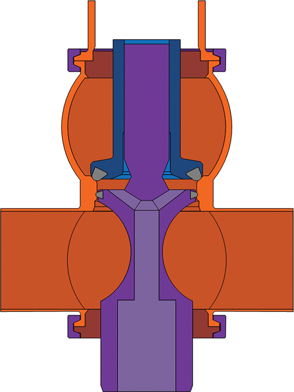
Figure 6. Mixproof valves combine the operation of two block valves and a bleed valve into a single unit, thereby decoupling simultaneous operations while reducing floorspace footprint
Decoupling transfer lines from tanks. A common transfer line can be cleaned more frequently than the supporting vessels if their cleaning paths are decoupled. A batch operation can be executed almost continuously by employing this separation scheme. A rolling simultaneous clean, processing, and dirty status can occur between vessels of the same family. The pseudo-continuous operation permits longer production windows. Vessels do not need to wait for the conclusion of production in an area prior to conducting CIP.
Added transfer flexibility comes at the cost of additional validation and programming. One should be cautious with overcommitting to transfer flexibility. The number of cleaning circuits can grow factorially to accommodate variable manufacturing transfer options. Operations can be restricted to select paths, or the combined circuits may be broken up into smaller pieces to fit the production schedule. A commission and validate “as needed” philosophy can be implemented to delay commissioning all variations at one time while avoiding future construction shutdowns.
Post-CIP air drying to extend clean hold times. At the conclusion of most biotech CIP programs, the equipment is allowed to drain completely, but water droplets will cling to the surfaces from surface tension. The warm damp air in the system boundary will eventually cool and condense long after the drain phase. Stagnant water within a clean system should be avoided as it provides the environment for bioburden to appear. Food plants will store lines in sanitizer to create a bacteriostatic environment. Another method in practice today to reduce residual water post-CIP to keep bioburden to a minimum and extend equipment clean hold timers is air drying.
Air drying can be achieved by iteratively pressurizing process vessels with dry air and venting. Pressurization is a heating process and causes more water to evaporate into the air. Upon depressurizing, the vapor will condense in suspension, having crossed the dewpoint via adiabatic cooling and evacuate from the vessel to the drain point. The cyclical pressurization-dilution method for pressure-rated vessels is more effective than passive open-path drying with clean air.
Positive pressure on the vessel should be maintained to avoid vacuum formation during the cooldown, which can pull contaminants into the system boundary. When venting to drains, it is important to not over-pressurize waste headers, which can impact adjacent simultaneous operations. Larger vessels can take in excess of one hour to air dry. Therefore, using a local dedicated air source will allow for the CIP unit to be released for other users and free up utilization.
Planning should be done for point-of-use air filtration for user local sources and cleaning boundaries. The retained heat in a vessel is the majority driver of the drying due to its thermal mass. Drying piping is more challenging, as it cools more quickly. Design considerations should be made to facilitate drying, such as avoiding parallel paths, confirming slopes, and ensuring venting locations are designated for circuit boundaries. The decrease in pooling water can safely validate an increase in clean hold times, reducing the total number of CIPs that must be performed.
Actualizing CIP sustainability
Regulatory guidelines, validation and commissioning requirements vary significantly by industry. Even with this considered, the discussed concepts can in part be adopted to provide value. Each action item individually will not provide immediate notable change, but embracing a sustainable CIP philosophy from the start of a project will pay significant dividends for years to come. A holistic CIP integration design approach is necessary to realize the opportunities that exist for reducing sanitary process consumables. Employing new vetted mechanical equipment, current best-design practices and streamlined automation will align a project for success.
VIEW THIS ARTICLE ON CHEMICAL ENGINEERING MAGAZINE.
For more information, contact Haskell’s Food and Beverage division leader, Keith Perkey.
Related News & Insights

How ECOncrete is Building a Sustainable Future for Coastal Infrastructure
Learn how a new round of funding is pushing marine construction technology worldwide. Discover sustainable solutions for building materials.

How a Madagascar Project Site Gamified Construction Safety Week
Learn how safety teams partnered with subcontractors and project teams to execute a week of fun-filled safety-themed games and activities.

An Adventure in Nantucket, Restoring Distillery Automation
Learn how Haskell Subject Matter Expert Alan Green brought custom solutions to Triple Eight Distillery to upgrade an overmodified system.

How AI and Digital Twins Are Shaping Industrial Analytics
Discover how stronger data foundations and planning tools are improving operations. Explore insights on capacity planning, supply chains and modeling.