Smart HVAC Design is Vital to Safe Food Production Environments

Learn how these five essential factors of airflow systems help ensure clean and safe food production environments and mitigate condensation issues.
Designing a food production facility requires owners and operators to thoroughly consider many factors — capital financing, access to raw materials, proximity to distribution points, the layout of process equipment, adequate staffing and employee welfare facilities to name a few. Not to mention all that goes into project longevity, like shifting standards for energy efficiency and regulatory standards with variable timelines.
No wonder airflow, the movement and filtration of an invisible gas within the facility, can get overlooked. Properly designed and installed airflow systems help ensure clean and safe food production environments and mitigate condensation issues.
While there are many nuances to airflow design, there are also unique considerations based on the type of facility, layout of the facility, height of the room, airflow obstructions and what is being produced in it; the more common considerations that apply to most facilities are:
- Air Distribution
- Filtration
- Pressurization
- Sanitation Purge
- Temperature/Humidity
Air Distribution
Good airflow design begins with proper distribution of the air. For the system to achieve the required performance for a safe food production environment, air distribution needs to be even throughout the production spaces, providing a platform for achieving proper filtration, pressurization, condensation control, temperature and humidity conditions. Access doors in the distribution ductwork are needed to access the interior of the ductwork for cleaning and swab tests. Ductwork should be located away from open product and not installed directly above production lines.
There are many cost-effective solutions to achieving good air distribution, particularly when designing a new facility. The best duct for maintaining cleanability is seamless round welded stainless steel. Round duct is easier to keep dry, clean and insulated. If budget constraints dictate, rectangular duct in stainless steel is acceptable.
The use of materials other than stainless steel should be reviewed and approved by the owner’s Quality Assurance/Quality Control (QAQC) professional prior to selection. A variety of air terminal devices (grilles, registers and diffuser boxes) are available depending on the application. Supplies and returns to production spaces should be equipped with drip pans. The drip pans should have heat-traced bottom covers to prevent condensation.
For interior installations, fabric duct (aka, duct socks) are a type of all-in-one duct and terminal device that offer advantages in both cost and performance. Fabric duct must be removed so that it can be cleaned and sanitized regularly. Most owners maintain two sets of the fabric duct so one set can be cleaned and sanitized while it is in service.
Most manufacturers of air terminals provide air velocity and distribution charts to ensure even air distribution. Velocities as low as 25 to 50 feet per minute (FPM) are typically adequate for controlling particulates, temperature, and moisture for spaces above 65°F.
For spaces below 65°F, terminal velocities should be in the 100- to 150-FPM range. Registers should supply air horizontally across the ceiling at velocities from 700 to 1,200 FPM. Designers should review the height of the space and analyze terminal devices to ensure they achieve adequate air movement in all areas of the production room. This can be done simply by drawing arcs around a dimensionally accurate plan showing the location of the terminal devices, representing the distance or ‘throw’ of each device. In spaces below 65°F, double deflection type diffusers and register grills will mitigate condensation and promote comfort.
Advancements in computational fluid dynamics (CFD) modeling now allow for precise planning and analysis of air distribution systems. Once considered for specialized applications, CFD models have become more affordable and user-friendly, making them practical for evaluating process air handling systems in food plants to ensure optimal performance. Airflow and velocity analysis provided by fabric duct manufacturers can aid in the final layout and sizing.
Another equally important aspect of even air distribution occurs on the return air side. If all the air returns in one location, air is more likely to short circuit and not distribute to all areas of the room. This can cause uneven temperatures, localized humidity issues and buildup of particulates. It is preferred to spread out the return air inlets and locate them in opposite elevations as supply air outlets (typically lower to the floor since most supply air is distributed up high).
When this cannot be accomplished, the selection of air devices should be done more carefully and include additional analysis of the overall distribution of air. This can be done by reviewing vertical sections of the building to see if the air devices can deliver air to the lower part of the spaces. It is recommended to consider a CFD model as it is necessary to ensure that airflow is evenly distributed.
Filtration
Filters are designed to remove contaminants from the air stream. These contaminants can come from the outside air (pollen, dust, products of combustion) brought in for ventilation purposes, from inside the space generated by the occupants or through the production process (powders, textile fibers, cooking oil). Advancements in filtration technology, such as high-efficiency particulate air (HEPA) filters, ultra-low penetration air (ULPA) filters, and activated carbon filters, provide enhanced removal of contaminants, ensuring better air quality and compliance with modern standards.
Filtration of gases can be particularly difficult in some cases, as being filtered is merely diluted. Carbon (like charcoal) is commonly used to remove gases, and there are other technologies, including ionic filters, that can also handle gases. More advanced options, such as electrostatic precipitators and molecular filters, have further enhanced the capability to remove fine particulates and gaseous contaminants efficiently.
Particulate control is the most common need for filters. In many facilities, there are product quality assurance (QA) staff who determine the amount of filtration required in each area. Each range of particulates is associated with different potential contaminants (e.g., pollen, textile fibers, mold). Knowing what the specific contaminants are and which will cause product issues, the QA staff can determine the specifications for the filtration system.
Sometimes, the user’s QA team will specify the minimum efficiency of the filters and air exchange rate to be used. The most common filter rating system in the U.S. is MERV (minimum efficiency reporting value), as defined by ASHRAE standards. MERV ratings represent the efficiency of removing particles of various sizes (e.g., from 1.0 – 3.0 microns, or 0.3 to 1.0 microns). Air exchange rates, sometimes referred to as air changes per hour, determine how often the air in space passes through the filters. Smart filtration systems that incorporate technologies, such as UV germicidal irradiation and photocatalytic oxidation, continuously monitor air quality and adjust fan speeds and filter replacements accordingly to maintain optimal air quality
In other cases, the concentration of particles of a certain size (e.g., less than 100 parts per million particles and greater than 3 microns) may be specified. In this case, each space’s filter efficiency and air exchange rate must be determined by calculations and experience in similar facilities.
Evenly distributed air is necessary to ensure that all the air in the space is being swept and all the particulates have an opportunity to be picked up by the return air systems. It is the return air system that brings all the indoor air and particulates to the filter banks. If you cannot get the particles to the filters, they will just keep circulating within the facility and concentrating.
Filtration for processing areas typically has a pre-filter and post-filter located in series within the airflow. The pre-filter has a MERV rating much lower than the post-filters. This acts as a sacrificial filter to increase the life expectancy of the post-filter and reduce the maintenance cost of frequent post-filter changes. In some applications, UV lights are used to further clean the air and provide the cleanliness required for the application.
Pressurization
Maintaining correct pressure relationships is critical for controlling airborne contamination in food production areas. Proper pressurization ensures that areas are protected from contamination by air from less clean areas. Advancements in pressurization technology, such as smart building management systems (BMS) and automated pressure control systems, have enhanced the ability to maintain optimal pressurization levels efficiently.
Many operators want to keep exposed, cooked foods positively pressurized relative to the raw ingredient or finished goods storage areas but find it challenging to do so cost-effectively. This difficulty can arise due to several factors, such as too many openings between spaces, insufficient outside air, or inadequate air handling equipment and controls.
The first step to ensuring proper pressurization is to determine the desired pressure relationships. Different areas in a plant that range from clean to dirty (e.g., raw product, cooking, ready-to-eat, packaging and finished/packaged product) typically require varying levels of cleanliness, and this results in different degrees of filtration and pressurization. The cleanest area is usually where the food-grade product is being packaged.
The building construction and layout are crucial in maintaining proper pressurization. The quality of the exterior and interior wall construction between spaces of different environmental conditions determines the ease of maintaining pressure. While there will be openings in the walls for product and personnel movement, unnecessary leaks can lead to air transfer and potential contamination.
Plant layout significantly affects the ability to maintain proper pressurization. A straight-line plant layout has advantages for airflow design but is rarely practical for overall space planning and operations. This layout avoids adjacent spaces with varying pressurization (e.g., a +1 next to a +3 and a +2). When this is not practical, airflow designs must accommodate multiple pressure zones adjacent.
One important but often overlooked factor in successful pressurization control is the sensor that monitors pressure between spaces. Some facilities lack sensors and rely on initial air balancing to maintain pressure relationships. However, these relationships can drift significantly due to variations in belt tension, filter loading, and equipment wear.
Rebalancing the air handling equipment frequently is impractical especially as outside air pressure varies with wind and weather changes, leading many facilities to fall short of their pressurization needs.
Air flows from one space to another due to differential pressure relationships and eventually flows out of the facility to the outdoors. Since what goes out must come in, outdoor air must be filtered and conditioned before it is introduced into the facility. The goal is to provide makeup air that replaces any exhausted air from a critical or noncritical exhaust or stack.
Typically, when unfiltered air infiltrates from the outside into areas like shipping/receiving docks, it leads to condensation and frost in adjoining areas of the facility that can become USDA- or FDA-critical food safety issues.
Some facilities install pressure sensors, control fans and dampers to maintain pressure relationships. This method can be effective if the right sensors are used. More than likely, poor-quality sensors with high inaccuracy and reliability issues are installed. This necessitates excessive outdoor air and frequent maintenance to keep sensors calibrated, just like relying on initial air balancing.
The best results will come from using highly accurate and reliable pressure sensors, such as those used in labs. For example, a high-quality sensor may cost $1,000 more than a typical sensor but save $10,000 in the initial cost of the air conditioning and thousands in annual energy costs. The correct sensor can reduce the need for outside air to one-tenth of what a cheaper sensor requires. These savings continue throughout the facility’s life, reducing energy costs annually. More importantly, proper pressurization is more reliably achieved throughout the building’s life without frequent rebalancing and recalibration.
Sanitation Purge
The sanitation shift in a food plant involves the use of large volumes of hot water. The entire room becomes saturated from the washdown which typically uses high pressure hot water to clean process equipment, production ceilings, floors and walls. Most rooms without a proper method for removing moisture develop fog, which can reduce visibility, causing worker safety and cleaning issues.
The amount of moisture generated during sanitation does not present an issue for the production room if it is dried and lowered to temperature at the beginning of the production shift. If the production space is not dry, this becomes an issue in federally inspected food processing facilities that will most likely result in lost production time.
Typically, after sanitation, problem spots will be water droplets remaining on the ceiling and overhead piping. Regardless of whether the water droplets are a result of the cleaning process or condensation, many rooms will require surfaces to be wiped dry daily before production begins.
The use of a critical process air handling unit(s) is the ideal way to control moisture during the sanitation cycle. These specific air handling units are designed with a cleanup cycle. The cycle provides 100% outside air to the production space while exhausting 100% of the moisture-laden air at the same time. This is accomplished using remote-mounted or unit-mounted exhaust fans that are powered and controlled by the critical process air handling units PLC control system.
At the end of the sanitation process, the unit is returned to production mode. Based on an adjustable time frame to help speed up the drying process, the outside air and return air from the room are cooled and reheated to lower the relative humidity of the incoming air. This method speeds the drying effect of the air as it is distributed horizontally across the ceiling. A reasonable amount of time is still required between the end of that sanitation process and the resumption of production to allow the room to dry and come down to temperature.
Temperature and Humidity
With proper air distribution and pressurization, temperature and humidity control become much easier to achieve. Different processes have different temperature and humidity requirements. They also introduce heat and moisture, which need to be removed to maintain the desired environmental conditions. These factors, along with weather conditions for the facility’s location, are considered in sizing the process air handling equipment that will serve the production areas.
In the past, it was less common for production areas to be air-conditioned, but a combination of process needs, the Food Safety Moderation Act (FSMA) and better environmental conditions for the personnel has led to more facilities providing air-conditioning.
As previously stated, pressurization requires outside air, which is often not in the desired temperature and humidity range for indoor conditions. Therefore, the outside air may need to be heated, cooled and/or dehumidified. In some cases, humidity may need to be added. Outside air intakes should be located as far away from sources of contaminants as possible. In most cases Process air handling units are located on the roof, where they are subject to heat and humidity.
Most commercial HVAC units are not designed to support food production facilities. It is important to determine the airflow and outside air needs first, then select the correct equipment for the application that can control temperature and humidity in all anticipated weather conditions. This may require multiple selections and often requires equipment with the ability to vary capacity over a wide range to handle the different load conditions the facility will experience.
Industrial process air handling units are designed to provide hygienic conditioned low-temperature mixed air and pressurization requirements for food production facilities. These units are equipped with MERV 7 prefilters and MERV 15 or higher final filters. Stainless steel-lined sloped and welded drain pans in each section of the unit are used to facilitate cleaning and condensate removal. The units are equipped with a stand-alone PLC control system, equipped with variable-frequency drive (VFDs) for the main fan and exhaust fan motors.
Condensation and moisture control are critical in most food production facilities given the potential for the growth and spread of bacteria that can result from standing water. Keeping the space dew point temperature below the coldest surface temperature prevents condensation. The space dew point is influenced by moisture from outside air and internal processes. The combination of outside and return air determines the heat and moisture removed by HVAC units to maintain desired conditions. Cold surfaces are typically insulated but may still be colder than the room, thus risking condensation if the dew point is not controlled. Using high volumes of heated air can help dry spaces after cleaning, reducing standing water.
Conclusion
Designing a food production facility today means embracing the latest hygienic air handling technologies to ensure a safe, efficient and compliant environment. Smart sensors, energy-efficient systems and advanced air filtration methods all play a critical role in maintaining optimal conditions. By staying current with these innovations, facilities can improve operational efficiency, enhance food safety and provide better working conditions for staff.
About the Authors
|
Paul Doege, Senior Refrigeration Engineer |
Doug Stricker, Design Director for Refrigeration |
| Doug Stricker is the Design Director for Refrigeration, and Paul Doege is a Senior Refrigeration Engineer. The Haskell colleagues have nearly 40 years of combined experience assisting large industrial clients. Contact them to discuss your upcoming capital project or challenges at your existing facility. | |


Paul Doege is a Senior Refrigeration Engineer. The Haskell colleagues, Doug Stricker and Paul Doege, have nearly 40 years of combined experience assisting large industrial clients. Contact them to discuss your upcoming capital project or challenges at your existing facility.

Written by Mandy Brawley
Related News & Insights
An Adventure in Nantucket, Restoring Distillery Automation
Learn how Haskell Subject Matter Expert Alan Green brought custom solutions to Triple Eight Distillery to upgrade an overmodified system.

How AI and Digital Twins Are Shaping Industrial Analytics
Discover how stronger data foundations and planning tools are improving operations. Explore insights on capacity planning, supply chains and modeling.
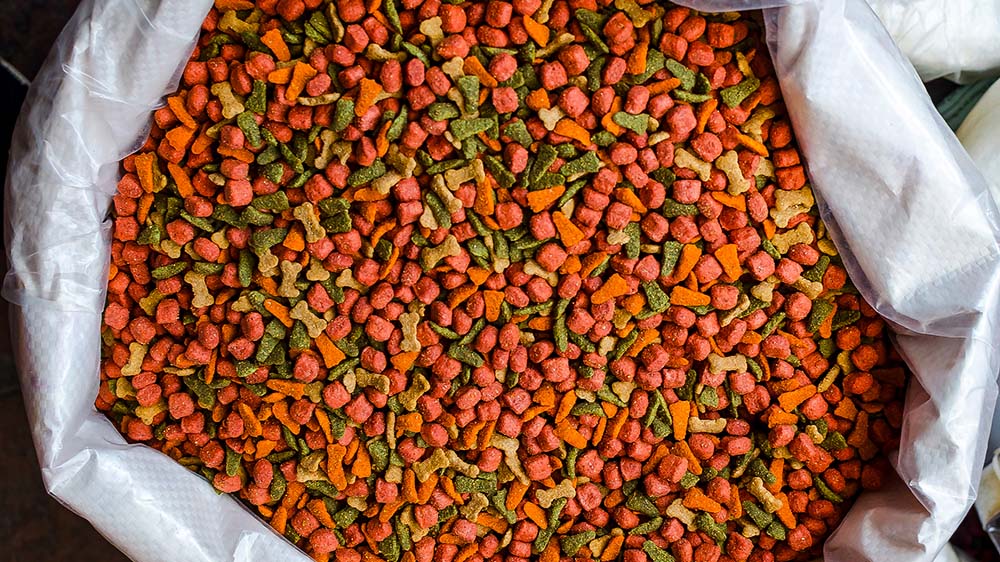
Natural Colors and Flavors: The New Standard in Pet Food
Learn how the industry is moving quickly to replace artificial ingredients and what manufacturers must do to maintain quality, compliance and throughput.
How to Control Glass Hazards in Food Manufacturing
Learn how to reduce glass contamination risks through prevention, inspection and maintenance best practices. Protect food safety and product quality.